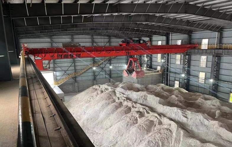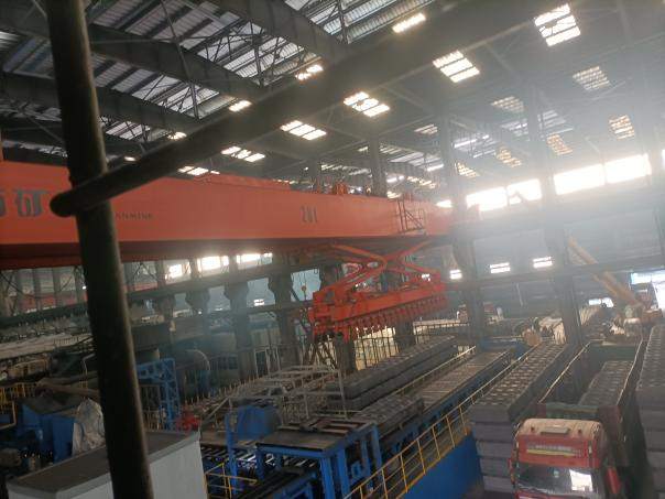

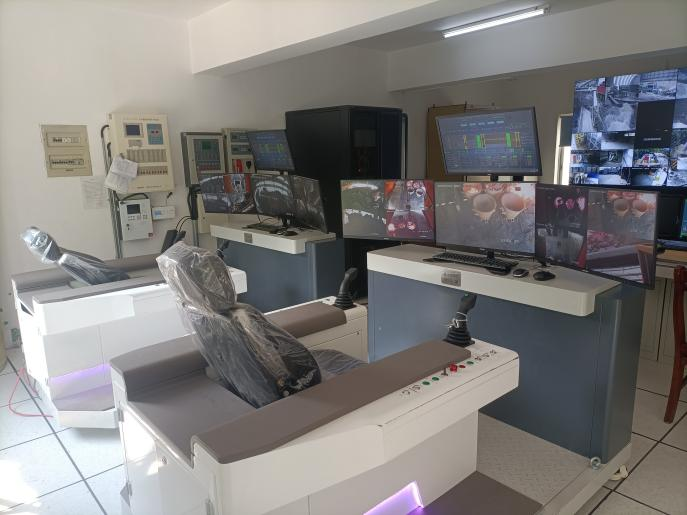

In response to the actual production situation and meeting production needs, a certain vehicle has a manual control function in the driver's cab. Now, a remote manual control function in the central control room is added. Manual operations are carried out by operators on the remote control panel in the central control room, in conjunction with video surveillance systems and safety monitoring systems. Among them, the cabin operation and remote control console operation can be freely switched between the two states through a switching switch. And standby for remote monitoring function. The operator can remotely control the overhead crane from the remote control chair in the central control room based on high-definition video and remote instructions to perform unloading, lifting, slotting, and coordinating maintenance operations. This significantly reduces the labor intensity of employees, improves the working environment, enhances safety and efficiency, and allows them to work like office white-collar workers, enhancing their sense of belonging and solving the problem of difficult recruitment.
To ensure smooth network data, 5G+technology is used for linking. The upward speed of the crane network is required to be no less than 200Mbps, and the end-to-end reliability of the network should reach 99.9% or above. Using full 5G communication to cover the overhead crane area and remote operation center. 5G has the characteristics of high speed, large bandwidth, low delay and high reliability. It is precisely for the needs of the industrial Internet in connection diversity, performance difference and communication diversity. It can control the network waiting time at the millisecond level, ensure the precise control of the unmanned crane system, and make it possible to improve the level of safe production in the industrial manufacturing field.
The crane control and upper computer monitoring adopt a customized remote control system, which has strong operability, simple instructions, rich graphics, and dynamic display of the main mechanisms. Including the safety monitoring function of the crane, it also needs to have functions such as fault diagnosis, operation record query, historical data archiving, operation management, etc., which can monitor the driving status in real time without affecting the basic operation of the crane.
The system connects the control PLC of the crane through an industrial Ethernet cable, and collects various real-time data of the lifting equipment during operation into the management system. The collected business data, fault chain information, working status and other information are processed and stored, and the operation status of the crane is reflected through some dynamic and intuitive images. The function of reproducing faults when they occur is provided, achieving secondary backup of data, and supporting various functions such as multimedia printing, database storage, and information export.
User job statistics function; Support statistics, tabular display, and import to Excel archive for a user's login.
Ø Support statistics, tabular display, and import to Excel archive for all user logins.
Ø Support user login statistics and importing Excel archives by time period.
Real time display of the main circuit switch, contactor, and control circuit switch status.
Real time display of on-site wind speed, crane power on time, and working frequency.
The voltage and current values of the power supply system.
Real time display of the interlocking status of the crane door switch.
Real time display of abnormal power supply voltage, abnormal switch interlocking status, and total overcurrent fault alarm information.
Real time display of the working and stopping status of each institution.
Real time display of operational parameter information such as lifting weight, current, voltage, speed, position, and working time.
Real time display of various mechanical limits and software limit status.
Real time display of interlocking status of various switches, limits, etc.
Real time display of the fault status of each frequency converter.
Real time display of the main command operation status of each institution.
Display the connection status of various major devices more intuitively through pictures.
Trend of operating parameters at different positions.
Ø Support querying, archiving, printing, and other functions for running parameter trends by time period.
Ø Support various configuration functions such as increasing or decreasing the trend of operating parameters, displaying appearance, etc.
Ø Support real-time display of variable states and operating parameters in a tabular format.
Ø Support functions such as querying, archiving, and printing variables within tables by time period.
Ø Support various editing functions such as adding or reducing table parameters, displaying appearance, etc.
Display the communication architecture and configuration of the crane.
Real time display of communication status for each configuration device.
Ø Support basic communication fault diagnosis.
Communication interruption has an alarm prompt box function.
Real time display of fault alarm information.
Ø Support querying, printing, tabulation, and display of fault alarm information.
Ø Support querying and printing operation variables.
Ø Support variable, fault query, and archiving by time period.
Ø Support importing variable information and fault information into the database and performing operations in Excel tables.
The system comes with operation, maintenance, and user manuals, which are detailed, detailed, and complete. It is easy to operate and use without the need for electrical or computer knowledge.